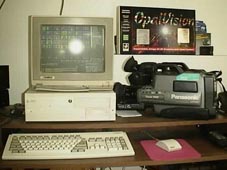
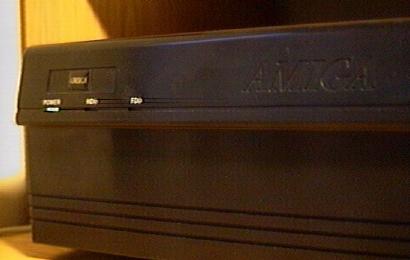
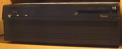
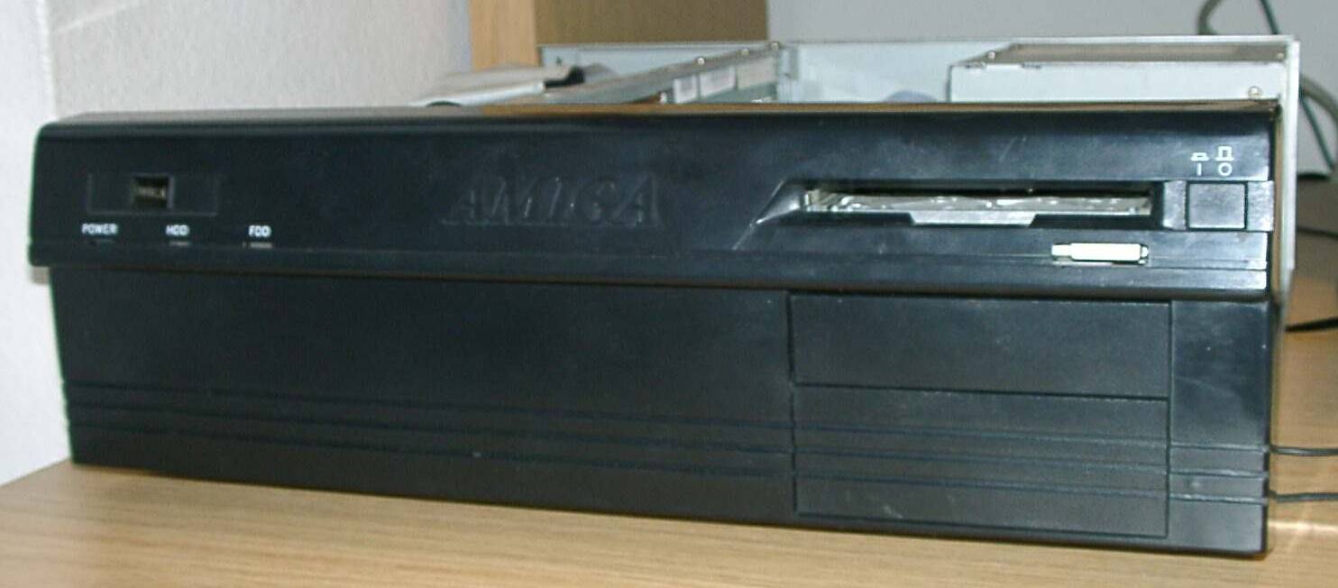
Picture of a very rare prototype black A4000. This is believed to be a very early unit which was only released to a hand full of developers such as Famo and Scala. It contains a revision 1 motherboard which has the option of taking an 030 in addition to an 020. It was also supplied with a revision 0 daughterboard. The case itself has no 5.25" drive bay as standard A4000's do. The case itself contains a power, hard drive and floppy LED.
Picture of Rev 1 Motherboard (1600 x 1200)
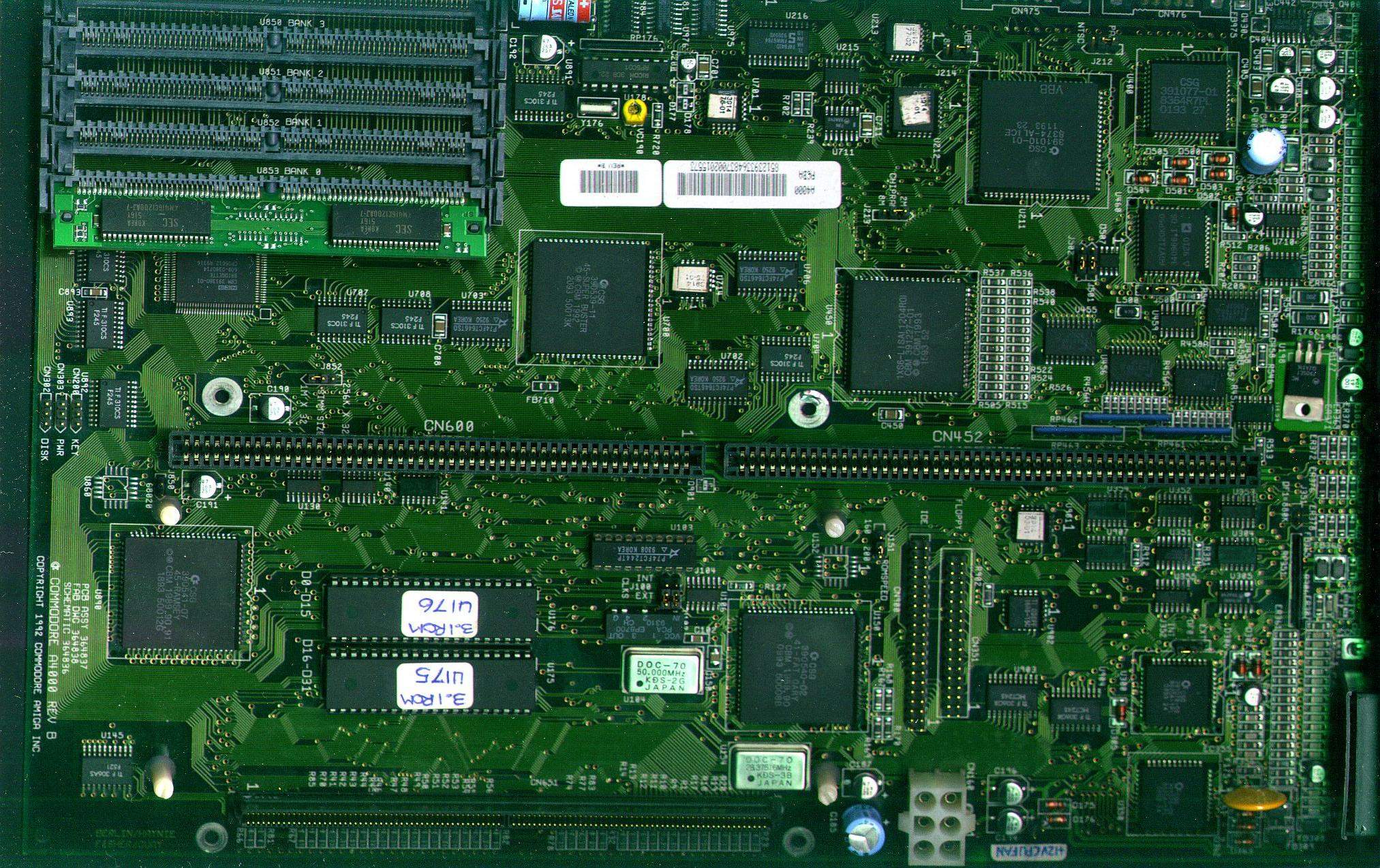
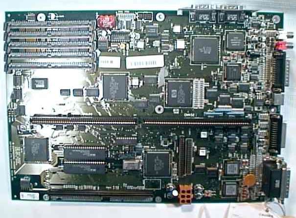
Picture of Rev B Motherboard, Front (2025 x 1274)
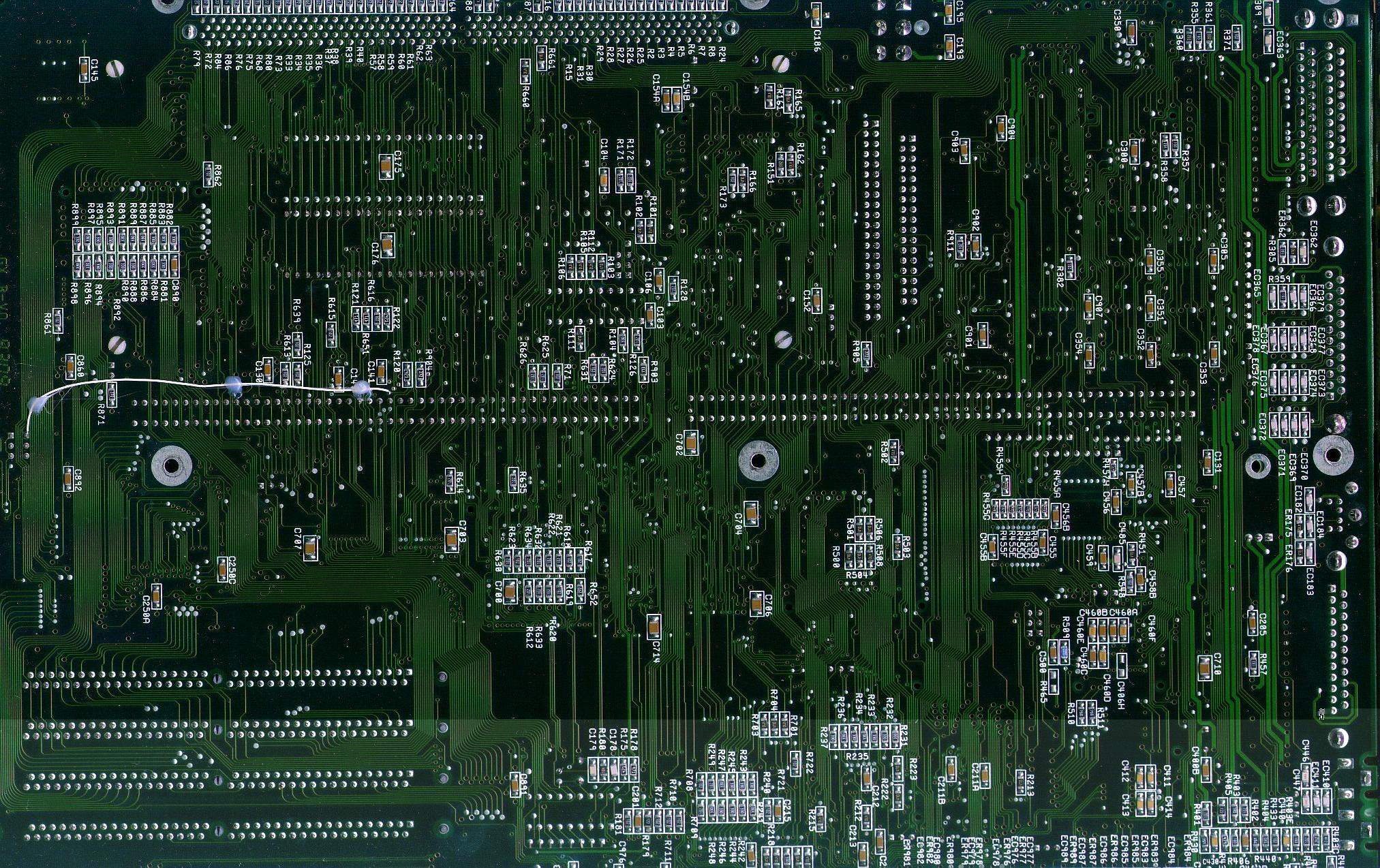
Picture of Rev B Motherboard, Rear (2025 x 1274)
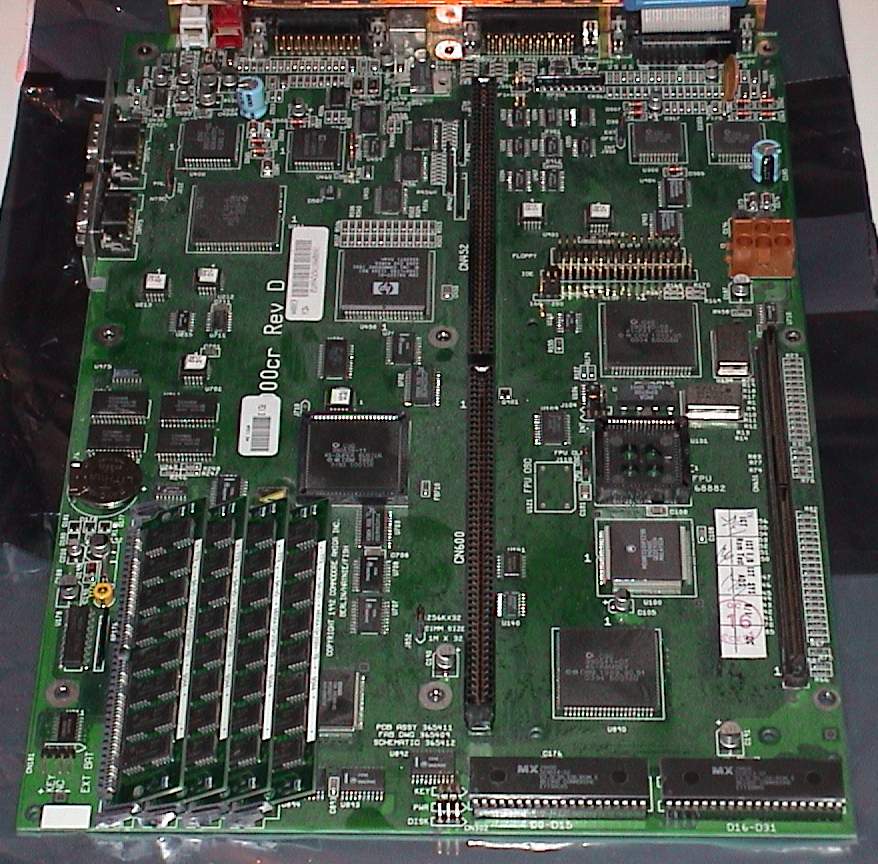
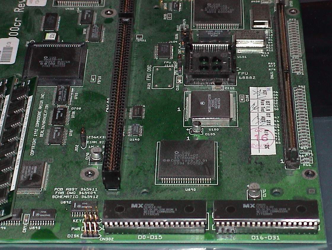
Picture of Rev D Motherboard, Image 1 (878 x 864)
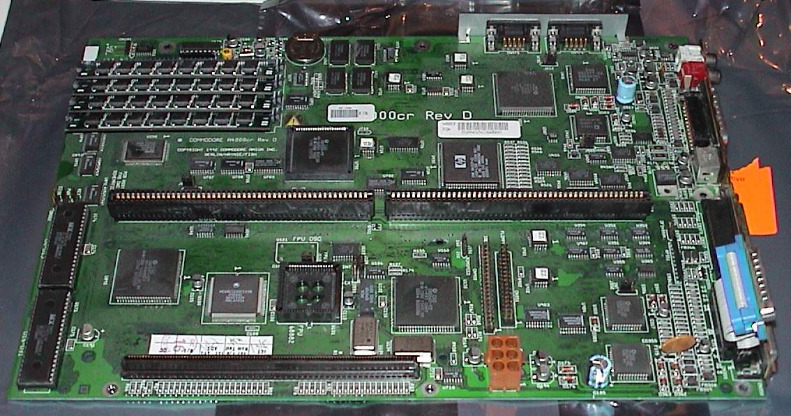
Picture of Rev D Motherboard, Image 2 (1134 x 596)
Picture of Rev D Motherboard, Image 3 (1120 x 844)
Picture of Rev ?? Motherboard, Image 1 (600 x 421) (ROMs missing)
Picture of Rev ?? Motherboard, Image 2 (605 x 445)
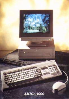
Hi Res Version of Black A4000 (1484 x 652)
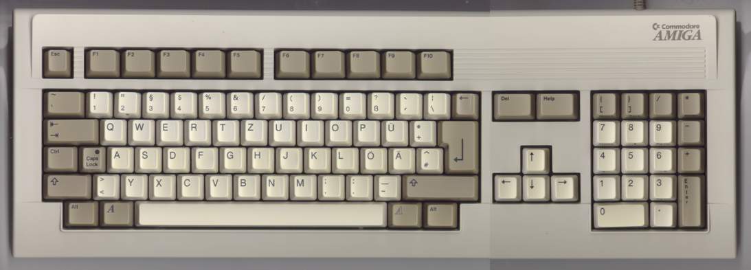
Picture of German A4000 Keyboard (1093 x 393)
A4000 Schematics (1.7MB)
Standard Specifications
| Case Type: | Desktop |
| Processor: | EC030@25Mhz (on motherboard for A4000-CR models) EC030@25Mhz via a Commodore A3630 040@25Mhz via Commodore A3640 |
| MMU: | None (030 versions) Internal (040 version) |
| FPU: | Optional, but not standard (030 versions) Internal (040 version) |
| Chipset: | AGA |
| Kickstarts: | V3.0 (2 ROMs) |
| Bus Controller: | Buster Rev 7 (Prototype A4000 only) Super Buster Rev 9 Super Buster Rev 11 |
| Expansion Slots: | 4 x 100pin Zorro III slots 1 x AGA Video slot (inline with Zorro) 3 x inactive 16bit ISA slots (inline with Zorro) 1 x 200pin CPU Fast slot. |
| Standard CHIP RAM: | 2MB |
| RAM sockets: | 4 x 72pin SIMM slots (A4000-CR only, 2MB Chip is surface mounted) 5 x 72pin SIMM slots (one slot is reserved for Chip RAM) |
| Hard Drive Controllers: | 1 x 3.5" Buffered IDE Controller |
| Drive Bays: | 1 x 5.25" (with faceplate, None for Black A4000) 4 x 3.5" (2 with faceplates) Note: Some machines were supplied with 1.5 times height floppy drives, in this case the second externally accessible 3.5" bay is fairly useless as it's only half height. |
| Expansion Ports: | 1 x 25pin Serial 1 x 25pin Parallel 1 x 23pin RGB Video 1 x 23pin External Floppy 2 x 9pin Joystick/Mouse 2 x RCA Audio (Left/Right) 1 x PS/2 style Keyboard Connector |
| Floppy Drive: | 1 x Internal 1.76MB Floppy Drive Note: Some machines were shipped with single height drives, others had 1.5 times height drives. |
| Motherboard Revisions: | Rev 1 (Early prototype, with black case) Rev B (Most Common) Rev D (A4000-CR) |
| Battery Backed Up Clock: | Yes, uses "Barrel" shaped batteries. |
The A4000 is often seen as the big brother of the A1200 but was targetted more at productivity users, rather than gamers. The A4000 was seen as a disappointment to many after the reception that the A3000 received. Although it uses a newer ROM and Chipset, the onboard SCSI-II had been replaced with a significantly slower IDE Controller and it did not contain the scandoubling hardware for attaching PC VGA type monitors which the A3000 did. However significant improvements were made to the Zorro III bus design (providing you had a Rev 11 buster) which fixed many problems that plagued the A3000, particularly with regards to bus mastering and DMA. The Keyboard connector the A4000 uses is fairly unique amongst big box Amigas, all other models used the large 5pin DIN Keyboard connector, however the A4000 uses a PS/2 style connector. Note however, that the connector is simply the same as the PS/2 connector uses on PCs, you must still use a dedicated Amiga keyboard, PC PS/2 keyboards cannot be used. The A4000 also includes a keylock which works by effectively removing the power from the keyboard and mouse. It is possible that some A4000's may have been released which contained 020 CPU's, as the A3630 which was supplied with some models can take an 020 instead of an 030 but this has not been confirmed. The motherboard also has provision for accepting an 020. There is one claim that Commodore donated an 020 based A4000 as a prize at The Gathering '92 and the organisers paid for an 030 upgrade out of their own pockets. A4000's with a Rev D motherboard differ slightly from the other versions and are dubbed "A4000-CR" which stands for "Cost Reduced". It was an attempt to reduce the cost of manufacturing the A4000. This was achieved by removing the SIMM slot intended for Chip RAM and soldering the RAM directly to the motherboard. Originally Commodore had plans to give the A4000 the ability to take up to 8MB of Chip, and so a SIMM slot seemed a good idea, however when it became clear this would never happen, it was removed to cut costs. All A4000s were given 2MB of Chip as standard and as this was the maximum it could address, the SIMM slot was never really needed. Another attempt to reduce the cost was to supply the 030 processor on the motherboard instead of on the A3630 processor card which other motherboard versions used.
Jumpers
| Function | Jumper | Setting | Description |
|---|---|---|---|
| CLK 90 Clock Source | J100 | 1-2 | Internal (020/030) |
| 2-3 | External (040) | ||
| CPU Clock Source | J104 | 1-2 | Internal |
| 2-3 | External | ||
| ROM Speed | J151 | 1-2 | 200ns |
| 2-3 | 160ns | ||
| CHIP RAM Size | J213 | 1-2 | 2MB |
| 2-3 | 8MB (Designed for future use, never used) | ||
| Second Internal Floppy | J351 | ON | No second internal floppy or 1.76MB Floppy |
| OFF | Enable second internal floppy as 880K as DF1: | ||
| Redirect DF0: | J352 | 1-2 | Internal DF1: and DF0:. External DF2: and DF3: |
| 2-3 | Internal DF1: and DF2:. External DF0: and DF3: | ||
| Enable DSACK | J850 | OFF | Required if CPU is 020. Also requires U860 and U152 |
| ON | No DSACK | ||
| RAM SIMM Size | J852 | 1-2 | 2MB or 4MB SIMMs |
| 2-3 | 1MB SIMMs | ||
| Video Type | J212 | 1-2 | NTSC |
| 2-3 | PAL | ||
| VBB/MA10 | J214 | 1-2 | Supplied VBB to Alice |
| 2-3 | Alices supplies MA10 for 8MB CHIP (Not used, for future expansion only) | ||
| Video Sync | J500 | 1-2 | Sync on Green Disabled |
| 2-3 | Sync on Green Enables | ||
| LISA Sync | J501 | 1-2 | RESERVED |
| 2-3 | DEFAULT | ||
| DAC Sync | J502 | 1-2 | DAC Syncs on Green |
| 2-3 | DAC uses standard signal |
Thanks to Greg Scott, Dave Haynie, Michael M Rye, Michael Czajka, Gruber Kristof, Andreas Loong and Claude Mueller