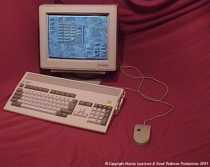
Picture of an A1200 showing Workbench 3.0 connected to a Microvitec 1438 monitor

Picture of an A1200 showing Workbench 3.0 connected to a Microvitec 1438 monitor

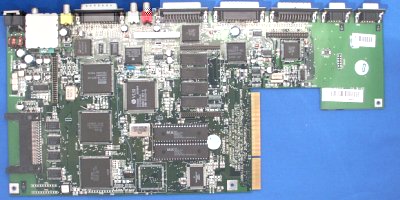
Picture of Rev 1A Motherboard
A1200 Revision 1A Motherboard (1204x616)
A1200 Revision 1B Motherboard (1226x622)
A1200 Revision 1D1 Motherboard (1415 x 2790)
A1200 Revision 1D3 Motherboard (1816 x 902)
A1200 Revision 1D4 Motherboard (3199x1588)
A1200 Revision 2B Motherboard (1206x620)
Specifications
NOTE: These specifications apply to the A1200 made by Commodore and do not necessarily apply to the A1200 made by Amiga Technologies.
| Processor | 020@14Mhz (on motherboard) |
| MMU | None |
| FPU | None (Some are rumoured to have been shipped in the US with 68882's but this is unlikely) |
| Battery Backed-Up Clock | No |
| Chipset | AGA |
| Standard CHIP RAM | 2MB |
| Motherboard RAM Sockets | None |
| Floppy Drive | Double Density (880K) Drive |
| Motherboard Hard Drive Controllers | Unbuffered 2.5" IDE Interface (can be converted for use with 3.5" devices) |
| External Connectors | Video (RGB) Mouse Joystick Serial Parallel Audio Left Audio Right RF Connector for TV Composite External Floppy |
| Expansion Slots | 1 x PCMCIA Type-II Card Slot 1 x Trapdoor expansion slot |
| Drivebays | 1 x Floppy Drive Bay 1 x 2.5" Drive Cradle |
| Kickstarts | KS 3.0 (two 40pin chips) (KS 3.1 is available as an upgrade) |
| Bus Controller | Budgie |
| Motherboard Revisions | Rev 0 (Engineering Prototype) Rev 1 (Advanced engineering prototype) Rev 1A (Initial Release) Rev 1B Rev 1D.4 (Budgie Rev -01 Release, E123C and E125C have been removed from motherboard) Rev 1D.4 (Budgie Rev -02 Release, additionally XR358 470Ohm resistor removed, 470Ohm resistor added to pin 43 of Alice) Rev 2B (Both budgie Rev -01 and Rev-02 were used. In addition to the changes in 1D.4 Resistor 118 was changed from 470Ohm to 220Ohm) |
| Standard Case Type | Computer in a keyboard |
The A1200 was considered the baby brother of the A4000 and was a very popular low-end machine of the early 1990's and is still popular among Amiga users today. It's probably the most common Amiga model still in regular use in vastly expanded forms. The A1200 came with a very poorly rated power supply (only 23w) so it was common practice to purchase third party power supplies or even use A500 power supplies (they are compatible) which have a higher wattage (65w?) because ven a slightly expanded A1200 would often suffer from power problems. For additional information, please see the Amiga Technologies A1200.
A1200 Schematics
|
PAGE 1 = Jumpers, Connectors, Signals, Revision History PAGE 2 = Processor and Custom Chip Interfaces and Signals PAGE 3 = Budgie and DRAM Interface PAGE 4 = Lisa and Video DAC Interface PAGE 5 = Paula, Audio Filters and Mouse and Joystick Interfaces PAGE 6 = Video and Audio Decoupling PAGE 7 = CIAs (VIAs) RS232 and Parallel Port Interface PAGE 8 = Floppy Controller and Gayle Schematics PAGE 9 = Keyboard MPU PAGE 10 = 16bit, 32bit, RTC and Optional Flash Memory Schematics PAGE 11 = Gayle and Memory Card PAGE 12 = Memory Expansion and IDE Controller PAGE 13 = Expansion Connector, Power Input, Termination and Test Access PAGE 14 = Gayle Schematic PAGE 15 = Alice Schematic PAGE 16 = Lisa Schematic PAGE 17 = A1200 System Block Diagram |
All files in the archive are standard IFF ILBM Images Download A1200 Schematics Thanks to Jaroslaw Kunert |
Thanks to Holger Hesselbarth, Greg Scott, Marius Lauritzen, Dr Spackel, NicDouille and Ian Stedman