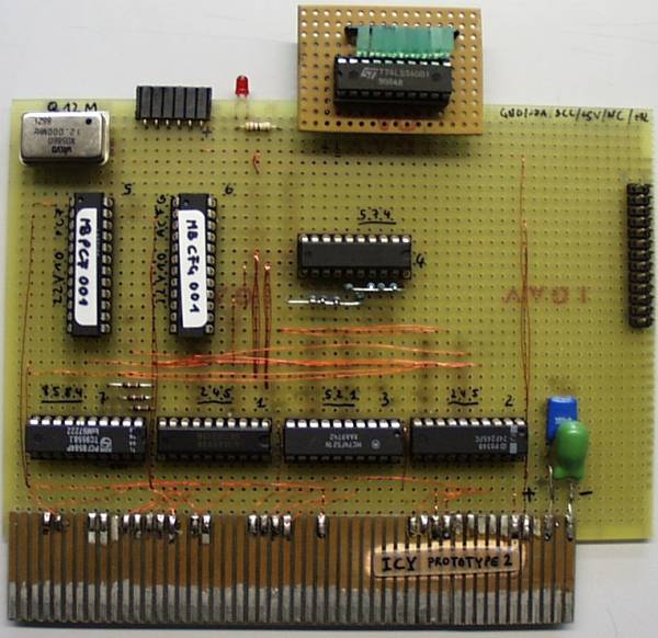
Picture of Prototype
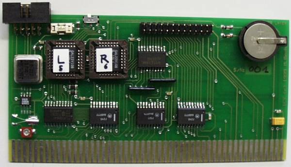
Picture of Final Version

Picture of Prototype

Picture of Final Version
ICY is a short Zorro II bus card implementing an I²C bus adaptor chip into the Amiga system. Compared to other Amiga Zorro cards, special care has been taken to design the hardware according to Commodore's hardware specifications. Full autoconfiguration with shutup capability and full relocability in address space is supported. All data and address lines are buffered to minimize bus load and allow clean working even in Zorro III busses.
Original site can be found here
Features
-easy bus interface: all accesses to the I²C bus are handled by the PCF8584 bus controller. No software based serial-parallel conversion, no speed critical routines, no need for adjustments.
- compliance with I²C specifications: the PCF8584 handles the I²C protocol completely in hardware. No accidental overclocking is possible, and bus speed can be chosen to be 1.5kHz, 11kHz, 45kHz or 90kHz.
- system conformity: the hardware design follows the Commodore guidelines for Zorro II PICs. Full autoconfiguration and buffered bus lines should ensure operation in all Zorro bus systems.
-expansion possibilities: ICY offers the possibility to enhance the system over an expansion connector. One module is already available, own modules can be added easily.
-RTC on board: a RTC has been included in the design and can optionally be used as a replacement for Commodore's fine RTC chips on the motherboards which tend to die after some years.
-buffered address and data lines for Zorro bus signals
-PCF8584 controller chip for hardware protocol actions
-interrupt driven communication possible
-seated GALs for easy updates
-version information of GALs readable via serial number
-expansion port for modules (/INT6 provided)
-RTC option for PCF8583 or DS1629 chip with backup battery
-fuse secured VCC (+5V) on I²C connector
-DTACK delay possibility for shacky design turbo boards
-double sided PCB with handrouted Eagle layout
Expansion modules
The ICY board offers an expansion port for small add-on modules. The port is compatible to the vmc isdn blaster expansion port and can be used for own small hardware modules. Moreover, the hyperCOM 3i module can be attached to ICY. This small module gives you two serial FIFO ports and one bidirectional parallel port. The latest driver release of vmc supports the 3i module completely, so ICY offers an easy and cheap way of expanding the I/O capabilities of each Zorro based Amiga. ICY is supported by Wilhelm Noekers i2c.library, which also supports other external interfaces. Many programs for I²C based hardware will work with ICY, as long as they use the i2c.library. Due to the simple register structure of the PCF8584, own software can also be written by users. Even AmigaBasic programs can handle this hardware port.
ICY expansion port technical documentation
The expansion port on ICY is realized as a 2x13 pinhead with 2.54mm spacing.
Pin 1 is located on the left side, towards the two seated GALs.
When designing a PCB, please mind that the backup battery, the seated GALs
and the resistor packs restrict usage of space. Make sure to avoid short
cuts between ICY and the expansion module.
Please mind that the current each PIC is allowed to draw is limited. According to the Zorro III specs, the following rules apply:
| VCC | 2 A |
| +12V | 500 mA |
| -12V | 60 mA |
| -5V | 60 mA |
When designing expansion modules, please mind that ICY also needs some current.
A "/" marks a lowactive signal, a preceeding "B" means buffered, bold letters mark the supply voltages.
| BD8 | 1 | 2 | BD9 |
| BD10 | 3 | 4 | BD11 |
| BD12 | 5 | 6 | BD13 |
| BD14 | 7 | 8 | BD15 |
| BA1 | 9 | 10 | BA2 |
| BA3 | 11 | 12 | BA4 |
| BA5 | 13 | 14 | BA6 |
| BA7 | 15 | 16 | BA8 |
| /INT6 | 17 | 18 | /BUSRST |
| READ | 19 | 20 | /UDS |
| /SLAVE | 21 | 22 | A15 |
| VCC | 23 | 24 | GND |
| -12V | 25 | 26 | +12V |
For further information on proper usage of these signals and timing restrictions (setup and hold times), please contact the author.
What is the I2C-bus? [From Phillips]
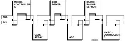
In modern electronic systems there are a number of peripheral ICs that have to communicate with each other and the outside world. To maximize hardware efficiency and simplify circuit design, Philips developed a simple bi-directional 2-wire, serial data (SDA) and serial clock (SCL) bus for inter-IC control. This I2C-bus supports any IC fabrication process and, with the extremely broad range of I2C-compatible chips from Philips and other suppliers, it has become the worldwide industry standard proprietary control bus.
Each device is recognized by a unique address and can operate as either a receiver-only device (e.g. an LCD driver or a transmitter with the capability to both receive and send information (such as memory). Transmitters and/or receivers can operate in either master or slave mode, depending on whether the chip has to initiate a data transfer or is only addressed. I2C is a multi-master bus, i.e. it can be controlled by more than one IC connected to it.
The basic I2C-bus, with a data transfer rate up to 100 kbits/s and 7-bit addressing, was originally introduced nearly 20 years ago. But, as data transfer rates and application functionality rapidly increased, the I2C-bus specification was enhanced to include Fast-mode and 10-bit addressing, meeting the demand for higher speeds and more address space.
The I2C-bus continues to keep pace with advancing technology while retaining its backwards compatibility. Mixed designs incorporating new low voltage devices are supported via the I2C-bus' level shifting capability. And, most recently, High-speed mode has been added; with speeds of up to 3.4 Mbits/s it ensures the capacity of the I2C-bus to support existing and future high speed serial transfer rates for applications such as EEPROM and Flash memory.
 m
m
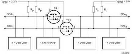
Philips Semiconductors has developed a simple 'level-shifting' enhancement to the standard I2C-bus, offering fully bi-directional data transfer between I2C-devices operating from different supply voltages. It provides an elegant solution for allowing ICs with different supply voltages to communicate and be controlled, for almost no additional design-in effort or cost.
The simple addition of two low-cost transistors, placed between the different voltage level sections of the I2C-bus, separates and transfers the logic voltage levels of the bus lines on either side of the level-shifter. In fact, with the addition of these transistors, the I2C-bus answers all level-shifting needs for a complete multi-supply voltage system design. This set-up also allows the level-shifter to be used to isolate a section of powered-down devices from the bus, allowing powered I2C devices to operate normally.
At the same time, the I2C-bus specification has been extended for devices operating below 2.7 V. This extension, together with compatibility of lower and higher voltage devices provided by the bi-directional level-shifter, ensures the I2C-bus will remain the serial bus of choice for future systems into the next century.
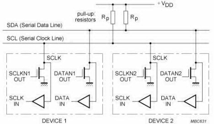
Until 1992, the I2C-bus was mainly used for the transfer of control and status information and its originally defined bit rate of 100 kbits/s remained sufficient for this purpose. As it became a de-facto standard, it began to be used for text and data transfer and to meet these needs, in 1992 the specification was upgraded with a Fast-mode, supporting bit rates up to 400 kbits/s. Compatible with Standard-mode devices, all Philips Semiconductors devices developed since 1992 have included a Fast-mode I2C-bus interface. Support for even higher data transfer speeds is now available through High-speed mode (which also offers the level-shifting enhancement).
High-speed mode I2C-Bus
Developments in high-speed serial RAMs and mixed technology telecom systems have created a demand for buses capable of operating at high speeds and with a variety of supply voltages. I2C's High-speed mode meets these needs without sacrificing its compatibility with existing Standard and Fast-mode devices or its low-cost simplicity - no special logic levels, timing or drive capability are needed.
A purpose-designed bridge in a High-speed mode master allows for bi-directional communications between Fast- and Standard-mode devices within a single I2C-bus system and, if required, this master can also perform bi-directional level shifting, supporting a variety of different voltage devices.
As a true multi-master bus, I2C's High-speed mode requires no additional wires or pins for slave devices. Also, there are two additional pins on a High-speed master which, if they are not used (because there is no system bridge or only Fast/Standard-mode are in use), then other I/O functions can be assigned to these pins, making I2C an extremely flexible solution.
10-bit I2C addressing
10-bit addressing allows the use of up to 1024 additional addresses to prevent problems with the allocation of slave addresses as the number of I2C devices rapidly expands. It does not change the format for addresses defined in the I2C-bus specification, using addresses reserved in the existing specification.
10-bit addressing does not affect the existing 7-bit addressing, allowing devices with 7-bit or 10-bit addresses to be connected to the same I2C-bus, and both types of devices can be used in Standard-, Fast- or High-speed mode systems.
Thanks to Michael Boehmer