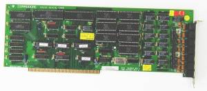
Picture of A2232 with connectors
Picture of A2232 with connectors
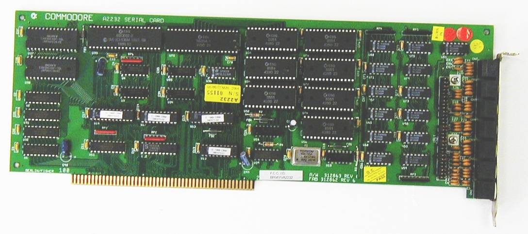
Hi Res Version of A2232 (1088 x 482)
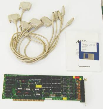
Hi Res Version of A2232 with connectors (798 x 846)
The A2232 is a full length Zorro II card which provides the Amiga with 7 additional RS232C serial ports. Each port can be driven independantly at between 50 and 19200 baud. There is however a driver available on Aminet which allows two of the serial ports to be driven at 115,200 baud with minimal CPU overhead. The A2232 has it's own 65CE02 microprocessor, operating at 3.58MHz, which controls the I//O and leaves the Amiga free for other tasks. Up to 5 A2232 Multiport Serial Cards may be installed in a single Amiga 2000/3000T. The board can actually be fitted with a faster crystal which will allow the ports to be driven at 38,400 or 57,600 using the orignal driver software
Serial Device Unit Numbers
| Unit | Port |
|---|---|
| 0 | Default Port |
| 1 | Amiga's internal serial port |
| 2 | Connector 1 on A2232 |
| 3 | Connector 2 on A2232 |
| 4 | Connector 3 on A2232 |
| 5 | Connector 4 on A2232 |
| 6 | Connector 5 on A2232 |
| 7 | Connector 6 on A2232 |
| 8 | Connector 7 on A2232 |
If two A2232 cards are installed in a machine, then the second card uses unit numbers from 9 to 15, the third card uses numbers 16 through to 22 and so on.
Jumpers:
The A2232 card has a set of jumper pins for each serial port. These jumpers allow you to change the pins that the Transmit Data (TxD) and Receive Data (RxD) signals appear on. The card comes with these pins set to transmit the data on DB25 pin 2, and to receive the data on DB25 pin 3. This setting is illustrated below.
Though the signal swapping should normally be done in the cable, you can alternatively swap these two signals via the jumpers. To set up a particlar A2232 port to transmit data on DB25 pin 3, and receive the data on DB25 pin 2, the jumpers should be set according to jumper set 1.
To change the jumpers from the original setting, locate the four sets of pins that correspond to the selected serial port. From the bottom edge of the card, the first four sets of pins correspond to the first port, the second to the second port, and so on.
Looking at the socket face:

 6 7 8
3  4  5
  1 2

1  TxD Transfer Data      6 Gnd  Ground
2  RXD Receive Data       7 DCD  Data Carrier Detect
3  RTS Request To Send    8 DTR  Data Terminal Ready
4  CTS Clear To Send
5  DSR Data Set Ready
Thanks to Greg Scott (National Amiga) and Ernst Zipfel